MMV1 Controls-Informed Structural Analysis: From Control Loads to Stress and Bending

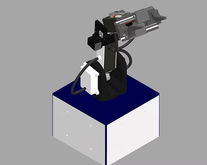
Let us discuss the structural calculations performed during the material-selection stage of the MMV1. In this section, I analyze the use of a 15 mm carbon-fiber rod as the primary shaft supporting the manipulator links.
To estimate the resulting shaft deflection under controller-derived loading, the analysis begins with the classical Jacobian relationship between joint-space torque and Cartesian force.

The diagram identifies the unknown support reactions used in the structural equilibrium model: Ay, Az, By, Bz, and the reaction moment Mx. These quantities are solved at each timestep from force and moment equilibrium in the local structural frame. All external loading in this model is generated by the Pontryagin-based control trajectory, meaning the bearing reactions are not arbitrary static loads; they evolve as a direct consequence of the controller-derived Cartesian forces acting through the manipulator structure.

The joint torques produced by the manipulator dynamics are treated as known time-varying quantities. Because the translational Jacobian of each MMV1 link is generally non-square, the Cartesian loading cannot be recovered through an ordinary matrix inverse. Instead, the Moore–Penrose pseudoinverse of the transposed Jacobian is used to obtain an equivalent Cartesian-force vector associated with each link.

For numerical implementation, a damped least-squares formulation may also be used when the Jacobian becomes poorly conditioned or approaches a singular configuration. The damping term λ regularizes the inversion and prevents excessively large Cartesian-force estimates caused by small singular values, while preserving the same joint-space-to-Cartesian loading relationship

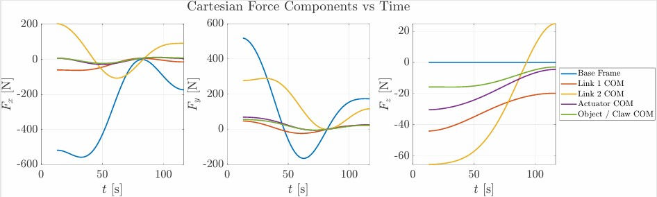
The resulting Cartesian force histories are consistent with the expected loading behavior of the MMV1 and are used as the external forcing for the subsequent structural analysis.
Once the Cartesian forces have been obtained, the loading is expressed in the local structural frame of the shaft. The magnitude of each link force is first calculated from its Cartesian (x), (y), and (z) components.

Next, the Cartesian loads are projected into the local yz-plane associated with the shaft. The magnitude of each link force is resolved along the local structural direction with φ = π/2

A local unit vector is then defined in the manipulator (yz)-plane. This frame follows the serial orientation of the robotic links and allows the controller-derived Cartesian loading to be represented in the plane relevant to the shaft bending analysis.

With the projected forces known, force equilibrium is imposed at every timestep. The external controller-derived loads are balanced by the reactions at the two shaft-support bearings, denoted by A(t) and B(t).


Moment equilibrium is imposed simultaneously using the projected position vectors of the manipulator components. The cross products between the local moment arms and projected forces determine the bending contribution of each load, while the applied shaft-axis moment is included separately. The unknown support reactions are collected into a single reaction vector containing the y and z-direction reactions at each bearing together with the reaction moment about the shaft axis. The equilibrium equations are assembled into matrix form:

The bearing reactions are then obtained by solving the resulting linear system. These reaction forces provide the boundary loading required to construct the internal shear-force and bending-moment distributions along the shaft.

To represent the discontinuities introduced by concentrated forces and bearing reactions, Macaulay functions are used. The Macaulay bracket activates each load contribution only after the shaft coordinate (X) passes the corresponding load location.
Using the bearing reactions and projected link forces, the time-varying shear field Vy is assembled in the local (y)-direction. Each controller-derived point load contributes a step change in the internal shear distribution along the shaft. The same procedure is applied in the local z-direction to obtain Vz.


Spatial integration of the (y)-direction shear field produces the corresponding bending moment Mz. Because the loading changes throughout the trajectory, the bending moment is a function of both shaft position and time.

Likewise, integration of the (z)-direction shear field produces the moment about the y-axis, My. These two bending-moment distributions are the quantities used directly in the Euler–Bernoulli deflection model.

For the 15 mm solid circular carbon-fiber rod, the second moment of area is calculated using

Because bending stiffness depends on the product (EI), the rod diameter has a fourth-power influence on its resistance to bending.
The bending moments are converted into local curvature using Euler–Bernoulli beam theory. Bending about the (z)-axis produces the corresponding transverse curvature through

Similarly, bending about the (y)-axis produces

The curvature fields therefore describe how the controller-derived loading bends the shaft locally at every position and timestep.
The raw (y)-direction deflection field is obtained through double integration of the corresponding curvature distribution. This converts local shaft curvature into transverse displacement along the complete supported span.

The same double-integration procedure is used to obtain the raw (z)-direction deflection field from κy.

Because the carbon-fiber shaft is supported at two bearing locations, the calculated deflection must satisfy zero-displacement boundary conditions at both supports. These conditions are enforced independently for the (y)- and (z)-direction deflection fields.


The integration constants are therefore represented as time-varying linear correction terms. Subtracting these terms from the raw solution produces the final bounded (z)-direction deflection field.
FEA Results/ Simulation
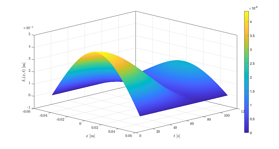
The surface shows the predicted transverse deflection field δz of the 15 mm carbon-fiber shaft throughout the PMP trajectory. The result provides a direct visualization of how the controller-derived loading bends the shaft over both position and time, allowing the structural adequacy of the selected carbon-fiber rod to be evaluated across the full trajectory rather than at only one static configuration.

The surface shows the predicted transverse deflection field δz(x,t) of the 15 mm carbon-fiber shaft throughout the PMP trajectory. The deflection is obtained by converting the time-varying bending moment My(x,t) into curvature through Euler–Bernoulli beam theory and then integrating twice along the shaft while enforcing zero-displacement boundary conditions at the bearing supports.
The result provides a direct visualization of how the controller-derived loading bends the shaft over both position and time, allowing the structural adequacy of the selected carbon-fiber rod to be evaluated across the full trajectory rather than at only one static configuration.
The predicted deflection is also qualitatively consistent with the physical MMV1 hardware. During operation, the selected 15 mm carbon-fiber shaft exhibited no significant observable bending under the manipulator’s self-loading, which agrees with the small deflections predicted by the analytical model. While no direct displacement measurements were taken to establish a formal experimental error metric, the physical behavior of the shaft provides supporting evidence that the structural calculations captured the correct order of magnitude and that the selected rod provided adequate bending stiffness for the MMV1.
A complementary finite-element analysis was performed on the MMV1 Link 1 enclosure using a representative 250 N load derived from the manipulator control and dynamics model.

The simulation evaluates the resulting von Mises stress distribution across the enclosure and its principal load-transfer regions. Material assignments included PLA, carbon-fiber-reinforced printed components, and brass threaded inserts to represent the major material interfaces present in the physical assembly.
The purpose of the FEA was not simply to generate a stress contour, but to apply a mechanically meaningful load obtained from the robot’s dynamics and control model directly to the structural design.
The FEA therefore provides a localized stress assessment that complements the analytical shaft calculations. While the Euler–Bernoulli model describes the internal shear, bending, curvature, and deflection of the supporting rod, the finite-element model evaluates how the controller-derived load is distributed through the surrounding enclosure geometry.
Together, these methods form a controls-informed structural-analysis workflow:

The analysis supports the conclusion that a 15 mm carbon-fiber shaft is appropriately sized for the MMV1 with respect to the bending loads evaluated here.
The accompanying MATLAB code, derivations, and supporting structural-analysis files are included below in the downloadable ZIP archive, as always!